The setup appearance window is opened by clicking the appearance button located along the bottom of the Setup window. In this window you can customize the appearance of the model and adjust the opacity settings for many of the components of the 3D model.
The buttons of this group switch between 3D surface and edge (ie wireframe) rendering.
Edges (wireframe)
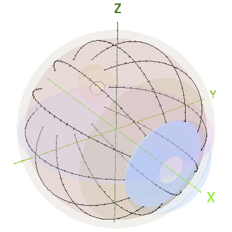
Translucent
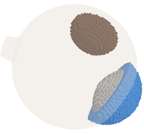
Opaque
The menus and buttons of this group modify the appearance of the Setup window in ways which may be of interest when preparing figures for publication and/or screen captures for educational purposes.
e.g. tissue voxels for lens, tumor and anterior chamber.
Some labels are rendered statically, their orientation is fixed with respect to an object in the scene, such as the plaque. Most labels are billboarded, their orientation always faces the viewer.
e.g. opaque plaque, translucent sources and tumor, suture guidance meridians and chords enabled.
The sliders in this group modify the opacity of the indicated object. An opacity of 1.0 is completely opaque, 0 is entirely translucent, 0.5 blends the object and background equally.