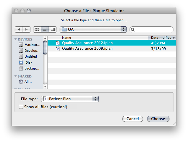
Open the 2012 QA .iplan file
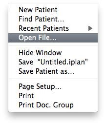
From the File menu:
A Quality Assurance (QA) procedure has been implemented to help assure that the software is operating correctly. You should run this QA test any time a dose calculation table and/or constant is modified or you receive a software upgrade. Copies of the QA file are located at Macintosh HD:Documents:Plaque Simulator Patients:QA:Quality Assurance 2012.iplan and/or Macintosh HD:Applications:Plaque Simulator Folder:Plaque Simulator Data:(Quality Assurance):QA:Quality Assurance 2012.iplan.
Select Open File... from the File menu and use the MacOSX file navigation services to find and open the Quality Assurance 2012.iplan file.
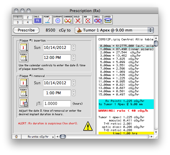
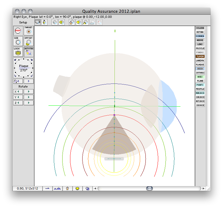
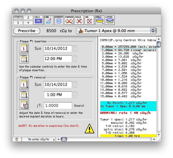
The 2012 QA plaque and prescription windows
The QA file creates a COMS style plaque with a single model 6711 I-125 source centered on the plaque's Central AXis.
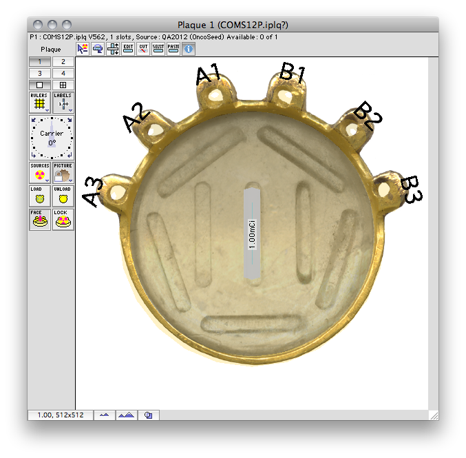
Normally, in a COMS plaque, the model 6711 seed center would be inset 1.4 mm from the concave face of the carrier. In this special case, however, the center of the seed is positioned exactly at the surface of the carrier. Because the carrier is in contact with the exterior slcera, the seed is also centered at the exteriors sclera. In this case, the seed is also centered at the base of a 9 mm tall tumor.
Plaque Simulator follows the COMS convention of measuring tumor height from the inner sclera which is assumed to be 1 mm thick, so a prescription (Rx) point at the apex of this tumor will be excatly 10 mm perpendicular to the center of the seed along its central axis.
In the Prescription window, the dose calculation algorithm buttons should be set to PS, point source, anisotropy disabled, with carrier, gold, air, shell and slots all disabled. The dose integration (T) time is one hour. The source activity is calibrated to 30 minutes after the implant begins. This simple setup is easily checked against a TG-43 hand calculation.
A dose rate of 1.225 cGy/h should be displayed for both the Rx point and at 10.0 mm in the Central AXis table. This value represents the dose rate constant for TG43U1 model 6711 seeds (0.965) multiplied by the apparent activity to air kerma strength conversion factor (1.27) and the radial dose function g(r) value at 10 mm (1.0). The dose rate constants and radial dose function for each isotope are loaded from the physics files at launch time. These values can be edited in the Constants and Radial Dose panes.
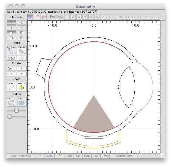
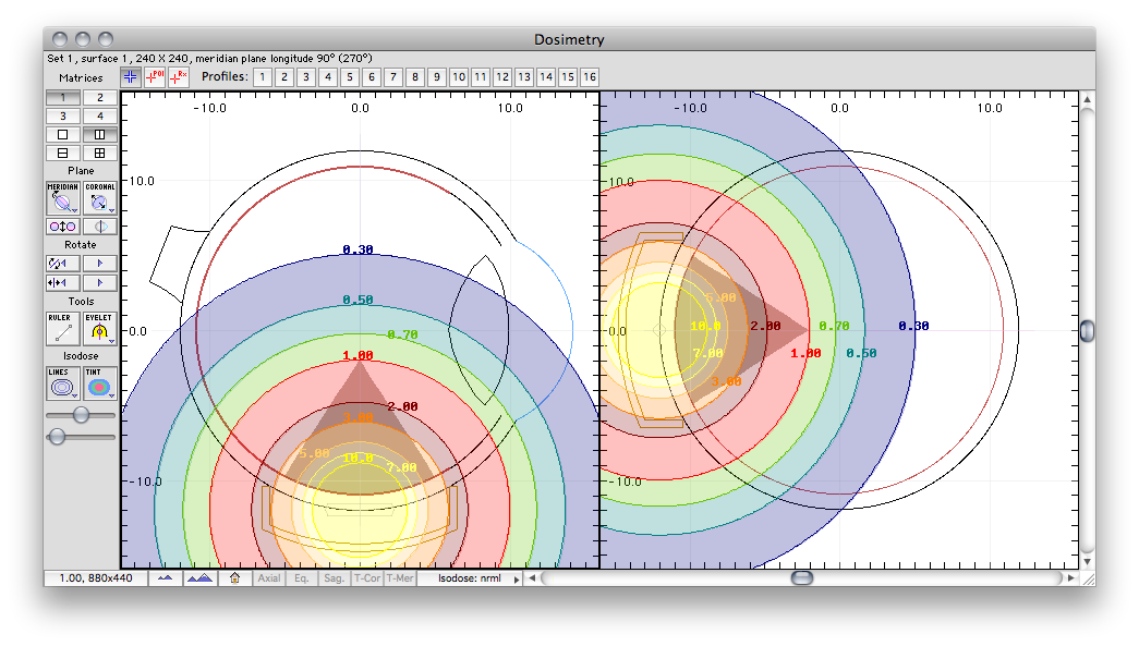
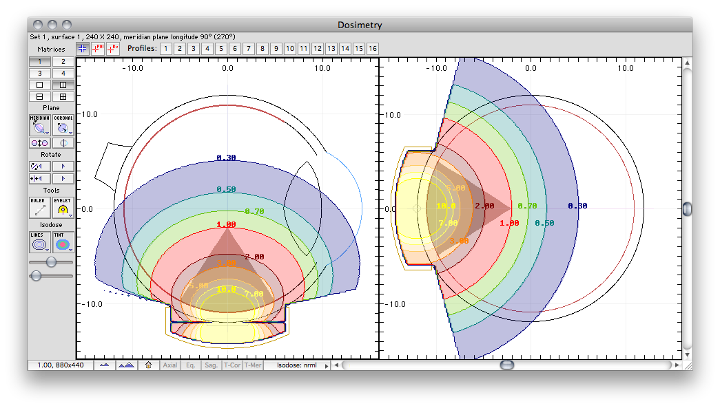
Planar isodose calculations for isotropic point source
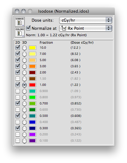
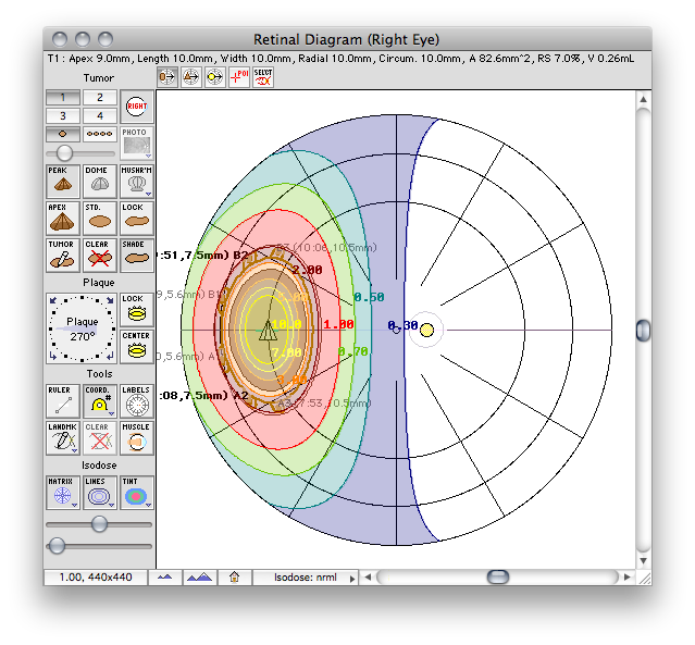
These are the normalized graphical results for a single isotropic point source. The isodose plots are normalized to a value of 1.0 at the Rx point, 10 mm from the plaque surface on its central axis.
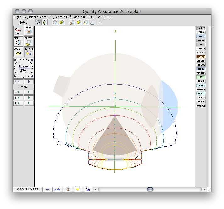
Planar isodose calculations for anisotropic linear source
For a more comprehensive QA check, enable anisotropy correction by clicking the Isotropy button in the Prescription window. The dose rate at 10.0 mm should not change since F[φ] should equal 1.0 at 0 degrees. The dose rate at 0.00 mm may change. Plaque Simulator checks for division by zero and substitutes a value of 0.0001 for zero distance in divisions.
Next, click the Point button in the Prescription window. This enables linear sources and the button changes to read "Line". Treating the source as linear will reduce the dose rate by approximately 1% at 10 mm and 35% at 1 mm on the central axis compared to the point geometry calculation. Click the Line button again to return to Point geometry.
Activating Shell collimation should have no effect since central axis points are never obscurred by the shell of the plaque. Toggling between Slot and Lip collimation should have no effect since a COMS plaque does not have collimating slots. For off axis points, hardcopy of the QA test is available by printing a dose table using the Dose tables document. These data can be compared to hand calculations.

Done
This completes the QA test procedure. If at any time the calculated dose rate is not within about 1% of a hand calculation, contact the distributor and the author for assistance and do not use this program for clinical calculations until the problem is resolved.