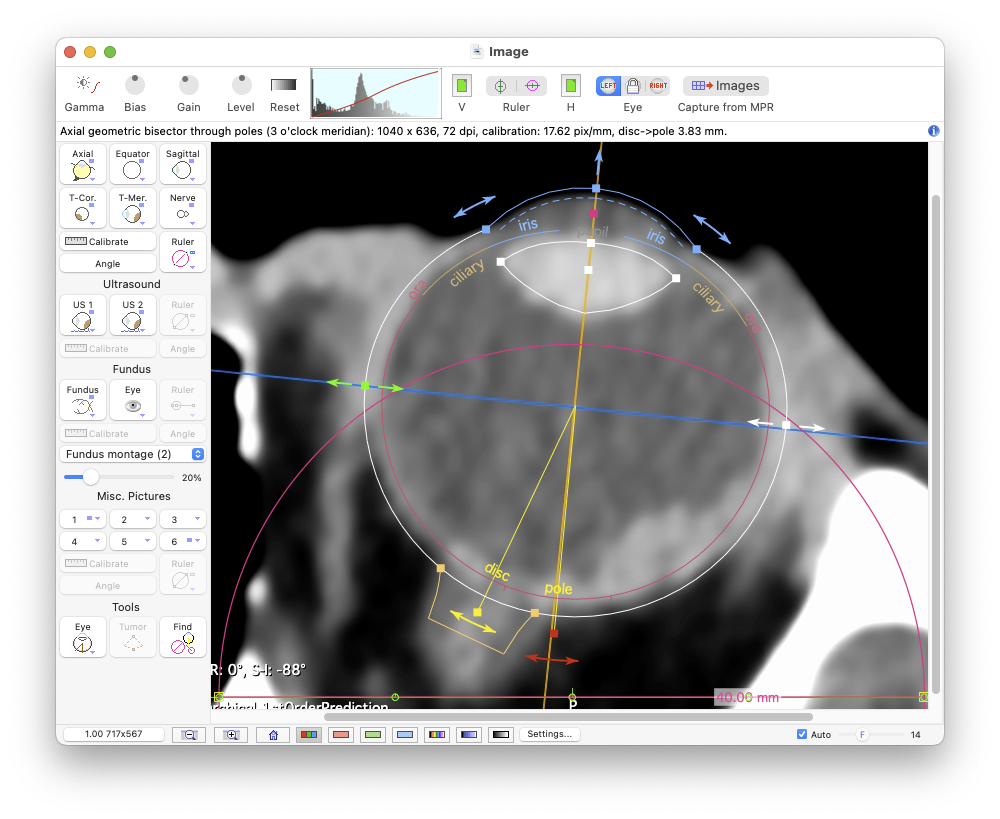
The Image Window

In the Image window, if you are NOT computing multiplanar reconstructions directly in Plaque Simulator's MPR window, the first task is to open Axial, Equatorial and Sagittal CT or MR planar reconstructions of the eye exported from another application such as Osirix. These images are used to measure the diameter of the eye at the equator, to determine the distance between the posterior pole and the center of the optic disc, and to estimate the curvature of the anterior and posterior hemispheres. Next, CT or MR images for a meridian plane (T-Mer.) and a coronal plane (T-Cor.) that intersect the tumor apex are opened. These images assist in determining the location within the eye of the tumor, especially tumors that are too anterior to be photographed by the fundus camera. Planar isodose calculations can also be overlayed on these images.

If you have loaded an axial CT series of the orbits into Plaque Simulator's MPR window then you will build your model of the eye via the MPR window and you can subsequently capture these images from the MPR window for inclusion in the treatment plan at a later time.

Next, one or two Ultrasound images are opened to document the tumor height and shape, such a dome or mushroom. A Fundus photo or collage of photos is then opened. The fundus photo collage is used to digitize the perimeter of the tumor base at the retina. Lastly, an optional frontal picture of the Eye may be opened. Suture guidance meridians can be projected onto this picture to assist the surgeon when marking the suture meridians.

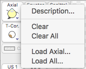
To load one or more image files use the contextual menu (control-click or use the right mouse button) associated with each image type

ImageAxialMenu

or simply drag and drop image files into the window using the MacOS Finder. If you drag a single image it will be loaded into the currently selected memory buffer. If you drag multiple images simultaneously they will be loaded into the memory buffer according to the PS image naming conventions. Many common image file formats are supported (e.g. JPG, PNG, TIFF, GIF). All images require a simple manual calibration procedure to determine the dimensions represented by an image pixel. The recommended software for preparing and exporting the multiplanar reconstructions (MPR) that PS expects is the OsiriX program.

Try to keep images under 1500x1500 pixels, there really is nothing to be gained by larger images, and the file size of .pdf documents becomes too large to send by email. When you save a patient setup file, a copy of each image is stored in .png format within the .iplan6 package, so file size can become large if the images are large. Images can be magnified using the "zoom" buttons at the lower left of the window, and you can pan using the scroll bar controls or by holding down the command key and "dragging".

Because Plaque Simulator imports images from many file formats, there is no practical way for the software to determine what kind of image it is opening other than having the user provide that information. The Axial, Equatorial, Sagittal, Tumor-Coronal, Tumor-Meridian, Ultrasound 1 & 2, Fundus and Eye buttons are linked to 9 offscreen image memory buffers that have been prepared for each type of image. You can open any kind of image into any of the memory buffers without damaging the program, but the results from a treatment planning perspective will be undefined.

Image window

The process is straightforward. For example, to load an axial reconstruction, select the axial image memory buffer by clicking the Axial button. PS will display the axial image if one has already been opened, or an empty window if the axial buffer is empty. To load an axial image, control-click the Axial button using the mouse (or trackpad) and keyboard or the functionally equivalent right mouse button and select Load Axial... from the contextual menu. This menu item launches a MacOS Finder navigaton services window from which you can navigate to and open the desired image file. You may also simply drag and drop an image file into the PS Image window from the MacOS Finder. Repeat this process for the other images. When opening a single image file, the file's name is ignored.

Shortcuts: If all of the images to be opened adhere to the PS file naming conventions you may simultaneously drag and drop a selection of images (up to 9 images), or, if the files are located in the same folder, the folder that contains the images onto the Image window. You may also option-click any image selection button or select Load All... from any button's contextual menu and use MacOS navigation services to open a group of images simultaneously. These links detail the file and calibration procedures for CT & MR images, fundus images and ultrasound images.

Note: The most efficient method of managing images is to follow the image naming protocol, organize all of the images associated with a patient into a folder named for the patient, and then simply drag and drop that patient folder onto the image window. If the treatment plan's patient name is currently empty, PS6 proposes a patient name derived from the parent folder within which the images are located. In PS version 6.3.3 a preference setting was added to the user preference pane which enables also automatically attempting to choose an institutional team preset when opening multiple images, e.g. by drag and drop. A team preset is proposed by comparing the name of the grandparent folder of the images to the list of institutional team preset keys. To use this new feature most effectively, adopt a protocol in which you use the same name for your institutional team preset keys as the institutional folders into which you organize your patients. For example, organize all patient folders for institution "USC" into a folder named "USC", and then create a team preset with key "USC". When interpreting parent and grandparent folder names and preset keys, any portion of a folder name or preset key, including and enclosed within () characters and any leading and trailing whitespace will be ignored. For example, "File Name (other info)" will be interpreted as "File Name".


Toolbar controls

Plaque Simulator supports two methods of image tonal adjustment: (1) Brightness & Contrast (BC), and (2) Gamma, which has controls for Bias, Gain and Level. In Gamma mode, slightly decreasing Gain and shifting Level is often very effective for enhancing scleral contrast in a CT image.

Toolbar

  • Gamma (vs Brightness & Contrast) - Toggles between the BC and Gamma methods of tonal adjustment.
  • Bias/Brightness - Turn knob CW to increase the Bias or Brightness, CCW to decrease.
  • Gain/Contrast - Turn knob CW to increase the Gain or Contrast, CCW to decrease.
  • Level - Turn knob CW to shift the Gamma Level setting to the right towards white, CCW to shift left towards black.
  • Reset - Resets the image tonal controls to their default settings.
  • V - The nominal color of vertically oriented rulers in MPR or ultrasound images. If the color of the calibration ruler in an image is not the anticipated green hue, you can sample the ruler color by clicking on this control to open the MacOS System Color Picker window. In the color picker, either select a color or use the magnifying eyedropper tool to sample the color of a ruler pixel in the image. This color control is disabled whenever a Misc. or Fundus group image is selected.
  • H - The nominal color of horizontally oriented rulers in MPR or ultrasound images. If the color of the calibration ruler in an image is not the anticipated green hue, you can sample the ruler color by clicking on this control to open the MacOS System Color Picker window. In the color picker, either select a color or use the magnifying eyedropper tool to sample the color of a ruler pixel in the image. This color control is disabled whenever a Misc. or Fundus group image is selected.
  • Ruler - Auto-initialize the PS6 MPR (e.g. CT or MRI) group or ultrasound group calibration ruler to either a horizontally or vertically oriented calibration ruler such as is found overlayed on reconstructions exported from Osirix. Horizontal rulers are usually best to use for calibration because the reconstructions used in eye plaque planning are usually wider than they are tall (in order to show the lateral and medial surrounding anatomy which is more interesting than air anterior to the cornea) so there are more horizontal tick marks to work with.

    This control becomes active only when a calibration ruler is enabled for an MPR or Ultrasound image. If all MPR images are scaled identically you can perform a single group calibration. The best MPR image to use for group calibrations is usually the axial image. Ultrasound images, and any MPR images that are not scaled identically, must be calibrated individually.

    The auto-fit function creates a monochrome image based on the ruler hue and tick mark settings found in the Images preferences pane. You can define independent or common tick mark and color (HSL) preferences for MPR images, US images, and horizontal vs vertical rulers. For example, the default settings for MPR reconstructions imported from Osirix are green hued rulers with 4 pixel long ticks and 10 mm tick mark spacing.

    The resulting monochrome image representing the green hued pixels is then searched for horizontal and vertical runs of contiguous dark pixels. The longest runs are assumed to represent the x and y ruler axes and the corresponding rows and columns in the image are then searched for tick mark patterns.

    Auto-init works best when the Osirix image magnification is adjusted such that a pair of horizontal ruler green tick marks are clearly visible to both the right and left side of the centermost tick (e.g. 5 total ticks covering a range of 40 mm). As a convenience, if auto-init is successful, the MPR group calibration sheet dialog will be automatically displayed and preset to propagate the calibration to all other MPR images. Click the OK button in that sheet to complete the calibration.

  • Eye - Select between modeling a left or right eye.
  • Capture from MPR - Immediately capture the six multiplanar reconstructions (axial. equator, sagittal, t-coronal, t-meridian and nerve) from the MPR image set if one has been loaded in the MPR window.

Any tick marks that the ruler auto-fit functions find are highlighted with green circles. Click on the pictures below to enlarge.

RulerAutoFitHoriz1

You can display the monochrome image that was created by the ruler auto-fit functions from the Image menu. This menu item toggles display of the 8-bit monochrome image generated by the ruler auto-calibration functions. It is used primarily to test and debug the algorithms that search the image for calibration rulers (e.g. green horizontal and/or vertical lines with tic marks). Adjust the ruler tick, hue and saturation settings and preferences for best results with your images. The default settings are optimized for images exported from Osirix and some common ultrasound systems.

RulerAutoFitHoriz2

Images preference pane
  • Contexts group:
    • MPR: - Define independent tick and hue preferences for MPR images.
    • US: - Define independent tick and hue preferences for US images.
    • Common: - Define common tick and hue preferences for MPR and US images.
    • Horizontal: - Define independent tick and hue preferences for horizontal rulers.
    • Vertical: - Define independent tick and hue preferences for vertical rulers.
    • Common: - Define common tick and hue preferences for horizontal and vertical rulers.
  • Tick marks group:
    • Spacing: - The spacing increment between tick marks for the selected contexts. For example, 10 mm spacing for MPR images and 1 mm spacing for US images.
    • Length: - The tick pattern length (in image pixels) to search for in the selected contexts. For example, 4 pixels.
  • Color group:
    • Color: - Select a basic color using the standard MacOS color picker window or using the provided hue angle slider. When searching an image for rulers, the HSL (hue, saturation, lightness) representation of color is used. The slider is limited to selecting hue angles in 10° increments which is adequate to select mid-green with a hue angle of 120°. For finer control, use the color picker.
    • Tolerance: - The color tolerance (range 0..±70°) expressed as hue angle. A larger tolerance allows for greater variation in the range of hues that will be considered to represent ruler pixels when creating the monochrome representation of the rulers in the image.
    • Saturation: - The minimum color saturation (range 0..1) value for a pixel to be considered a ruler pixel.
    • Lightness: - The lower and upper values of lightness (range 0..1) that are allowed for a pixel to be considered as a ruler pixel. Ruler lines may at times be blended with the background of the image to create smoother appearing lines. If the background is white, this can create false positives, resulting in horizontal or vertical lines in the monochrome image that are several pixels thick. Reduce the lightness range to create a sharper monochrome representation of the rulers in the original image.

RulerAutofitPrefs

The rulers controls group in Images preferences.


Multiplanar reconstruction (MPR) group
CTGroupEmpty

CTGroupAxial

The buttons in the MPR group are intended to select and calibrate multiplanar reconstructions such as CT and/or MR images. When an image has been loaded into an offscreen buffer, the button for that buffer will display a small, dark gray badge to the upper right of the button icon and the Ruler, Angle and Calibrate buttons become functional and may be optionally enabled.

  • Axial - Displays the axial image.
  • Equator - Displays the equatorial image.
  • Sagittal - Displays the sagittal image.
  • T-Cor. - Displays the coronal image that intersects the tumor apex. Use OSIRIX to create this image.
  • T-Mer. - Displays the meridian image that intersects the tumor apex. Use OSIRIX to create this image.
  • Nerve - Displays the nerve-coronal image.
  • Ruler - Enables display of the MPR calibration tool for the selected imported image. Adjust the diameter of the circle to a known distance in the imported image such as 40 or 50 mm. This button's contextual menu provides access to a customizable properties sheet for that image's rulers, an auto initialization utility and a slider to adjust the control handle size. The auto initialization utility searches the image for a bright green horizontal line with tick marks such as found in images exported from OsiriX, and if found, the calibration tool (ie ruler #1) is fit to that line. You may still need to fine tune the tool prior to calibration if the tick marks are obscured by text. Option-clicking this button also invokes the auto initialization utility when the tool display transitions from disabled to enabled. NOTE: MPR images created by PS from 3D CT and MR image sets are automatically calibrated when the reconstruction is calculated.
  • Angle - Modifies the ruler calibration tool to display additional distance and angular measurements.
  • Calibrate - Opens the image calibration sheet in which is entered the diameter of the primary ruler calibration tool in mm.

Ultrasound group
USGroup
  • US 1 - Displays ultrasound image #1.
  • US 2 - Displays ultrasound image #2.
  • Angle - Modifies the ruler calibration tool to display additional distance and angular measurements.
  • Calibrate - Opens the ultrasound image calibration dialog in which is entered the diameter of the ruler tool in mm.
  • Ruler - Enables display of the ultrasound calibration ruler tool. Adjust the diameter of the circle to a measured distance in the image such as the tumor base or height. You can customize the appearance and control handle size from this button's contextual menu.

Ruler contextual menu - Edit ultrasound calibration ruler tool parameters.
USGroup

  • Size slider - Adjusts ruler control handle size.
  • Saturation (H) slider - Adjust the minimum ruler color saturation setting for horizontal auto-fit. If auto-fit is not finding a ruler in the image and the pixels representing the ruler appear washed-out try reducing the saturation setting.
  • Saturation (V) slider - Adjust the minimum ruler color saturation setting for vertical auto-fit.
  • Show Ruler GWorld - Enables display the monochrome image that was created by the ruler auto-fit functions. Adjust the ruler tick, hue and saturation settings for best auto-fit results with your images. If this item is enabled the saturation sliders will update auto-fit in real time to help determine the oiptimal settings.
  • Properties... - Opens the ultrasound rulers properties sheet. Here you can display additional rulers and edit their appearance.

USGroup

Fundus group
FundusGroupFundus

FundusGroupEye

  • Fundus - Displays a fundus camera photo, montage of photos, or a wide angle SLO picture (e.g. Optos).
  • Eye - Displays the eye picture for iris and ciliary tumors.
  • Ruler - Enables display of the fundus calibration or the eye picture meridian compass tool. Place the pole labeled end of the fundus calibration tool over the posterior pole, the other end over the center of the optic disc. For fundus collages, drag the collage center markers to the center of each collage component. For eye pictures, drag and size the meridian compass to fit the limbus. You can customize ruler appearance and control handle size from the ruler button's contextual menu.
  • Calib. - Opens the fundus ruler calibration sheet in which is entered the distance between the disc and pole in mm. This distance is automatically calculated by the eye sizing tool. From this dialog you can also remove the background from the collage (typically black or white) by assigning a transparency color. Note: the eye picture ruler does not require calibration because it only displays meridian plane angles.
  • Angle - Modifies the fundus calibration or eye compass ruler to display the meridian angle compass. The compass markings may optionally be configured to display clock hours or toric axis angles using items located in the contextual menu of the ruler button.

  • Fundus projection menu - FundusProjectionMenu This menu selects the number of fundus camera pictures that were stitched together to make a fundus collage (e.g. Collage (3 centers)). Raw, wide angle, Scanning Laser Ophthalmoscopy (SLO) images are typically stereographic projections and you may get better mapping of image pixels to 3D space and to the retinal diagram which is an azimuthal equidistant projection by designating the raw projection type as stereographic (conversion of stereographic projections to azimuthal equidistant was introduced with PS version 6.7.9). As a convenience, when loading a batch or a folder of images, images that use the naming convention fundus will be initialized as single photos and images that use the naming convention optomap will be initialized as stereographic projections.

  • Collage slider - Optionally adjust the diameter of the collage picture range tool.
Image window with fundus

Misc. pictures group
MiscGroup

Miscellaneous pictures are provided for documentation purposes only, they can not be calibrated or used in any quantitative way in the plan. They may, however, be printed on page 6 of the treatment plan via document preference settings.

  • 1 - Displays miscellaneous picture #1.
  • 2 - Displays miscellaneous picture #2.
  • 3 - Displays miscellaneous picture #3.
  • 4 - Displays miscellaneous picture #4.
  • 5 - Displays miscellaneous picture #5.
  • 6 - Displays miscellaneous picture #6.

Tools group
ToolsGroup
  • Eye - Enables display of the eye sizing tool on MPR and ultrasound images. You can customize the eye tool's control handle size and enable/disable its anatomic labels and dragging cues from this button's contextual menu. The label size slider found in the footer controls group adjusts label font size.
    EyeToolMenu
    DraggingCues

    When control handle dragging cues are enabled the dimension being changed will be illustrated during the drag.

  • Tumor - Enables display of the tumor angle and height tool on the T-Meridian image. With this tool you can drag the tumor base (dark brown) control handle along the inner scleral surface to mark the approximate location of the tumor as it appears in the T-Mer. image. This location is saved as the T-Meridian tumor angle, an angle in the meridian plane between vectors originating at the eye origin and pointing towards the tumor base and the posterior pole. The Meridian tumor angle is displayed in the Eye Size window. The Meridian tumor angle is only used to help PS decide which direction to rotate the meridian dosimetry plane about the AP axis when auto-centering the plane, it does not reposition the tumor. The tumor tool is best used only after the tumor base position has been finalized. Note: the beige colored apex control handle of the tumor tool does change the tumor height, but it is limited to the vector pointing from the tumor base towards the eye origin. If the tumor is not symmetric about this vector, set the tumor apex from the Retinal Diagram window. In general, the tumor height is best set manually based on ultrasound imaging. This tool is enabled by default for T-Meridian images.

  • Find - Brings offscreen tools back into view.

AxialToolWithLabelsAndCues

Axial tool with both anatomic labels and cues.


AxialToolWithCues

Axial tool with only dragging cues.


TMerToolExample2

T-Meridian tool with both labels and cues.


AxialToolWithLabels

Axial tool with only anatomic labels.


AxialToolNoLabels

Axial tool without anatomic labels or cues.


TMerToolExample

T-Meridian tool with only dragging cues.


Footer controls
Footer

WndwSize
Opens the Window Size Dialog dialog.

ZoomOut
Zoom out
Halves the screen size of an image pixel.
ZoomIn
Zoom in
Doubles the screen size of an image pixel.
Home
Home
Displays the image as 1 screen point per image pixel.
color
Color
Displays image in 32 bit (ARGB8888) color (8-bit alpha, red, green and blue components).
color
Red
Displays the red component of the RGB image in 8-bit monochrome (256 shades of gray) mode. For example, Optos SLO images consist primarily of red and green components.
color
Green
Displays the green component of the RGB image in 8-bit monochrome (256 shades of gray) mode. For example, Optos SLO images consist primarily of red and green components.
color
Blue
Displays the blue component of the RGB image in 8-bit monochrome (256 shades of gray) mode. For example, Optos SLO images consist primarily of red and green components so after selecting to display only the blue components, the image will appear as a nearly all-black monochrome image.
color
Auto-tone
Auto Tone is similar to Auto Contrast in that it also darkens the darkest pixels to pure black, lightens the lightest pixels to pure white, and redistributes all the other tonal values in between, but it does so on a channel-by-channel basis, meaning that the Red, Green and Blue channels each receive their own separate boost in contrast.
color
Auto-contrast
Auto Contrast looks at a composite of the three (Red, Green and Blue) color channels (in other words, it treats all three as if they were a single grayscale image) and darkens the darkest pixels to pure black, lightens the lightest pixels to pure white, and redistributes all the other tonal values in between.
monochrome
Monochrome
Displays images in 8-bit monochrome (256 shades of gray). RGB colors are converted to 8-bit grayscale using either the averaging formula gray = (red + green + blue) / 3 or the weighted formula gray = 0.299 red + 0.587 green + 0.114 blue if weighted conversion item is enabled in the Image menu.
SettingsBtn
Opens the Images preference settings pane where you can customize ruler auto-calibration settings. You can also double-click within the image content region of this window to open the Images preference settings pane.
AutoFooterBtn
Enables automatic scaling of tool labels as a function of window frame size and zoom magnification.
LabelSizeSlider
Slider manually adjusts the font size used for tool labels for each image context (this slider becomes active when the auto scaling checkbox is disabled).