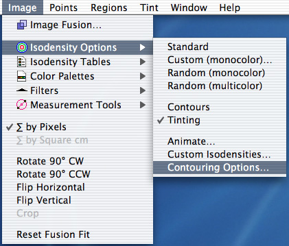
 To perform isodensity contouring click the Contour button. The Contour button simultaneously enables the Contours and Tinting items in the Isodensity Options menu, and the Isodenity button. You can also enable/disable these items individually if you wish. Normally, only isodensity tinting is enabled since it is much faster than contouring. Isodensity contours, which are similar to the altitude contours you might find on a geological survey map, are useful when trying to find tissue surfaces and for mapping radiation dose distributions on film.
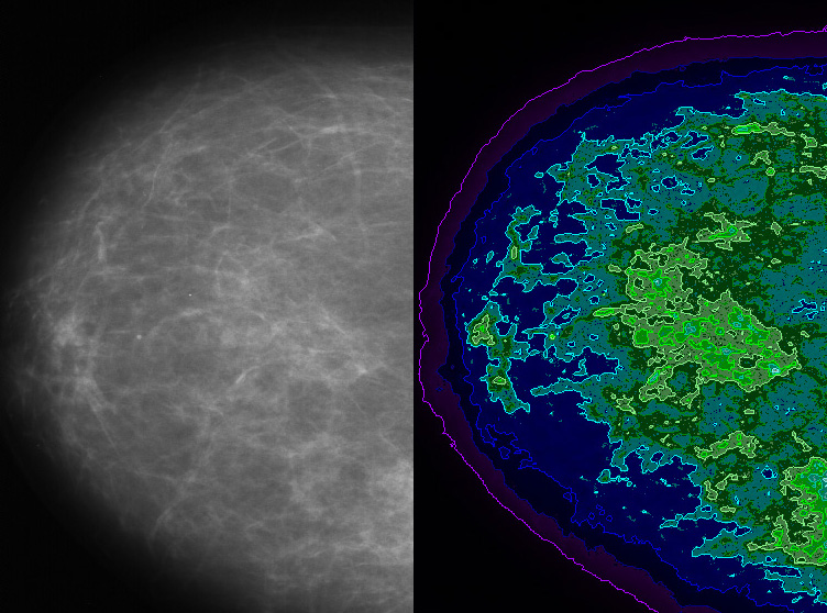
The pictures below illustrate isodensity contouring of a mammogram.
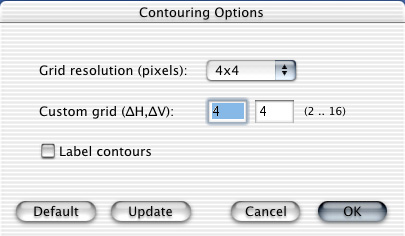 The Contouring Options dialog allows you to set the contouring grid to sizes from 2x2 pixels up to 16x16 pixels. The smaller the grid size, the more precise the contour will be, but the calculation will take longer. The program defaults to a 4x4 grid at startup. Click the Label contours button to label the contours. Labeling is off by default.
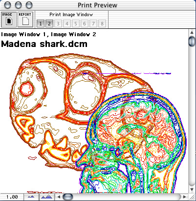
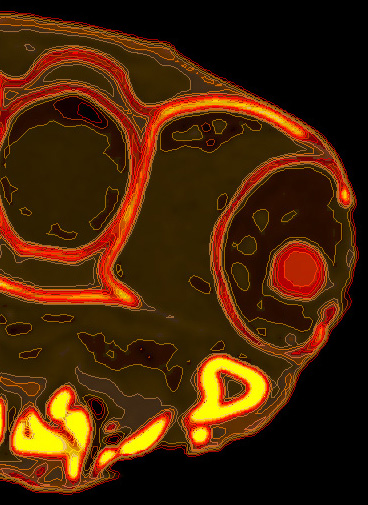
The next picture is an example of isodensity contouring the shark head DICOM image in the sample files.
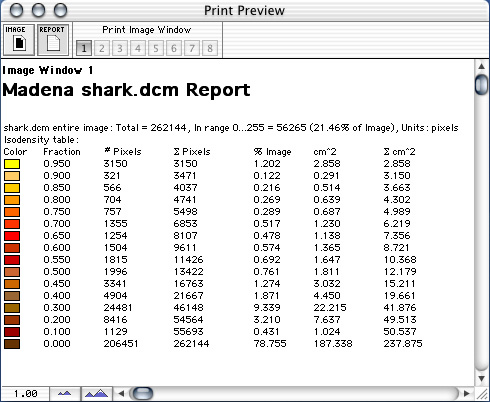
Analysis of the isodensity tinting is printed on the Report document and can be viewed in the Print Preview window.
Isodensity contours from multiple image windows can be superimposed on one another on the Image document. The underlying image pixels have been removed in the example below by disabling image pixels in the document preferences dialog.